Table of Contents
ReVolt Guitar - User Guide
3-Channel All-Analog Guitar Amp Simulator
Thank you for purchasing ReVolt Guitar, you’re about to embark on a world of next-generation tonal possibilities!
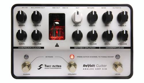
From sublime cleans to the gnarliest of Metal tones, your performance demands the pinnacle in tonal excellence.Enter ReVolt Guitar, a forward-thinking all-analog 3-channel preamp primed to serve as the beating-heart of your rig. The latest-iteration of Two notes’ critically- acclaimed preamp solutions has been engineered with a singular mission: to empower players with the ultimate in foundation tone. Forget any preconceptions of a run-of-the-mill amp-in-a-box: ReVolt Guitar stands-apart. It’s inspired by a trio of iconic amps; It’s fuelled by 200V and genuine tube power; It’s born to assimilate into a myriad of usage scenarios; It cuts above the rest with its integrated OD-Boost circuit.Two notes’ gets it: Your Tone Matters. Why settle for anything short of perfection?
The complete electronic version of this manual, as well as the Two notes Audio Engineering software and hardware products, are subject to updates. You can download the most recent versions of the products on the Two notes Audio Engineering website.
This manual describes ReVolt Guitar and provides instructions for its operation. It is highly recommended that you read this document before using the product. The contents of this manual have been thoroughly verified and it is believed to accurately describe the product at the time of shipment from the factory or downloaded from our website.
Two notes Audio Engineering is a registered trademark of:
OROSYS SAS
76 rue de la Mine
34980 Saint-Gély-du-Fesc
France
Tel: +33 (0)484 250 910
Fax: +33 (0)467 595 703
Contact and support: http://support.two-notes.com
Website: http://www.two-notes.com
This document is the exclusive property of OROSYS SAS. In the interest of product development, OROSYS SAS reserves the right to change technical specifications, modify and/or cease production without prior notice. OROSYS SAS cannot be held responsible for any damage, accidental or otherwise, that results from an inappropriate use of the Torpedo Captor X Please refer to the safety instructions included in this manual. The reproduction of any part of this document is strictly forbidden without the written authorization of OROSYS SAS.
All product names and trademarks are the property of their respective owners. Product names and trademarks found in this document were used during the development of ReVolt Guitar but are in no way associated or affiliated with OROSYS SAS.
Foreword
1. Important Safety instructions
- Before using the product, it is necessary to carefully read and consider the following information. Keep this document in a safe place; it is important for the protection of both the user and the product. If any malfunction of the product is suspected, Two notes Audio Engineering advises seeking the assistance of a qualified technician.
- Please verify that the voltage required by the mains power adapter matches the voltage specifications of your country. If not - or if unsure - do not connect the product to the wall outlet. This could result in damage to the mains power adapter, the product and injury to the user. This product must not be used when there is lightning present. In case of severe weather with a risk of lightning, unplug the power adapter to reduce the risk of electric shock and fire. The mains power adapter provided with the product complies with the standards of the country where you purchased the product. If a replacement is needed, please use a standard compliant mains power adapter.
- ReVolt must never be used near a heat source, near a flame, in the rain, in damp areas or near any liquid of any sort. When transporting the unit, care needs to be taken to avoid any shocks that could result in damage requiring the assistance of a qualified technician.
- Always use a dry and soft cloth with no alcohol or solvents for cleaning. Please keep the unit clean and free from dust
- All maintenance operations must be carried out by service centers approved by Two notes Audio Engineering or by qualified technicians. Never attempt to repair the product by yourself.
2. Package Contents
The shipped package contains:
- One ReVolt unit in a protective sleeve
- One power adapter
- One ⅛” TRS jack-to-MIDI Type-A adaptor
- One quickstart guide
The complete electronic version of this manual, alongside the manuals for Torpedo Wall of Sound and GENOME are subject to change. You can download the most recent versions of the bundled software and the related user guides on the Two notes Audio Engineering website.
3. Declaration of Conformity
Manufacturer: OROSYS SAS
Category of product: Analog audio signal processor
Product: ReVolt
Test Manager: Guillaume Pille
The Two notes ReVolt is certified to be compliant to the CE and FCC standards:
- EN 55103-1 : 1996 and EN 55103-2 : 1996.
- EN 60065 05/2002 + A1 05/2006.
- EMC directive 89/336/EEC and Low Voltage Directive 73/23/EEC.
- FCC Part 15 : 2008.
- ICES-003 : 2004.
- AS/NZS 3548 class B for Australia and New Zealand.
- IEC : 2008 - CISPR 22 class B.
4. Disposal of Waste Equipment by Users in Private Household in the European Union
5. Warranty
OROSYS SARL warrants that this TWO NOTES AUDIO ENGINEERING product shall be free of defects in parts and workmanship when used under normal operating conditions for a period of two (2) years from the date of purchase. This warranty shall apply to the original purchaser when purchased from an Authorized TWO NOTES AUDIO ENGINEERING dealer.
IMPORTANT: PLEASE RETAIN YOUR SALES RECEIPT, AS IT IS YOUR PROOF OF PURCHASE COVERING YOUR LIMITED WARRANTY. THIS LIMITED WARRANTY IS VOID WITHOUT YOUR SALES RECEIPT.
Defective products that qualify for coverage under this warranty will be repaired or replaced, (at OROSYS SAS’s sole discretion) with a like or comparable product, without charge. In the event that warranty service be required, Please contact your authorized TWO NOTES AUDIO ENGINEERING dealer in order to obtain an RMA to return the complete product to the Authorized TWO NOTES AUDIO ENGINEERING Service Center closest to you, with proof of purchase, during the applicable warranty period.
Transportation costs to the service center ARE NOT INCLUDED in this limited warranty. OROSYS SAS will cover the cost of standard ground return transportation for repairs performed under this warranty.
This limited warranty becomes void if the serial number on the product is defaced or removed, or if the product has been damaged by alteration, misuse including connection to faulty or unsuitable ancillary equipment, accident including lightning, water, fire, or neglect; or if repair has been attempted by persons not authorized by OROSYS SAS.
Any implied warranties, including without limitation, any implied warranties of merchantability or fitness for any particular purpose, imposed under state or provincial law are limited to the duration of this limited warranty. Some states or provinces do not allow limitations on how long an implied warranty lasts, so the above limitations may not be applicable.
OROSYS SAS ASSUMES NO LIABILITY FOR PROPERTY DAMAGE RESULTING FROM ANY FAILURE OF THIS PRODUCT NOR ANY LOSS OF INCOME, SATISFACTION, OR DAMAGES ARISING FROM THE LOSS OF USE OF SAME DUE TO DEFECTS OR AVAILABILITY OF IT DURING SERVICE.
In case you must absolutely send your TWO NOTES AUDIO ENGINEERING product to any other location, it is of vital importance that you keep the original packing materials. It is very difficult to avoid damage when shipping the product without these materials. OROSYS SAS is not responsible for damages caused to the product by improper packaging and reserves the right to charge a reboxing fee for any unit returned for service without the original packing material.
THE FOREGOING CONSTITUTES THE ONLY WARRANTY MADE BY OROSYS SAS WITH RESPECT TO THE PRODUCTS AND IS MADE EXPRESSLY IN LIEU OF ALL OTHER WARRANTIES EXPRESSED OR IMPLIED.
ReVolt Guitar Key Features
- 3-channel guitar amp simulator featuring an all analog signal path
- Inject some warmth and bite into your tone courtesy of a 12AX7 preamp tube running at high voltage
- Integrated OD-Boost circuit with dedicated switching and level control
- Expertly engineered Analog Cab Sim for seamless DI whether it’s in the studio or on stage
- 4-Cable mode, FX Loop and MIDI In/Out for effortless integration into existing setups
- Robust, made-to-move design that’s perfectly sized for pedalboards and fly-rigs
- Includes a lifetime licence to Wall of Sound and GENOME, the final word in digital app- and plugin-based tone-shaping for the forward-thinking player (VST/AU/AAX/Standalone)
- Includes the ReVolt: Series-G DynIR Cabinet Collection (valued at 100€/$) featuring 10 exquisite DynIR captures inspired by leading guitar amplifier brands
1. Top Panel
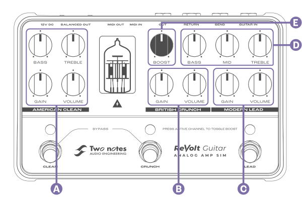
A - AMERICAN CLEAN
| Name | Function |
|---|---|
| BASS | Adjusts the passive low frequency voicing section. As the knob is rotated the signal is attenuated (down to -26dB) or boosted (up to +6dB), below 100Hz. |
| TREBLE | Adjusts the passive high frequency voicing section. As the knob is rotated your signal is attenuated (down to -13dB) or boosted (up to +12dB), above 1.5kHz. |
| GAIN | Adjusts the amount of gain feeding the AMERICAN CLEAN channel. Increasing the gain can lead to signal distortion, and in extreme cases, unwanted clipping. |
| VOLUME | Adjusts the output volume of the AMERICAN CLEAN channel, the volume is positioned pre the FX Loop. In the instance unwanted clipping occurs, try lowering the volume to ensure any subsequent devices in your signal path are not overdriven. |
B - BRITISH CRUNCH
| Name | Function |
|---|---|
| GAIN | Adjusts the amount of gain feeding the BRITISH CRUNCH channel. Increasing the gain can lead to signal distortion, and in extreme cases, unwanted clipping. |
| VOLUME | Adjusts the output volume of the BRITISH CRUNCH channel, the volume is positioned pre the FX Loop. In the instance unwanted clipping occurs, try lowering the volume to ensure any subsequent devices in your signal path are not overdriven. |
C - MODERN LEAD
| Name | Function |
|---|---|
| GAIN | Adjusts the amount of gain feeding the MODERN LEAD channel. Increasing the gain can lead to signal distortion, and in extreme cases, unwanted clipping. |
| VOLUME | Adjusts the output volume of the MODERN LEAD channel, the volume is positioned pre the FX Loop. In the instance unwanted clipping occurs, try lowering the volume to ensure any subsequent devices in your signal path are not overdriven. |
D - Shared EQ for BRITISH CRUNCH / MODERN LEAD Channels
| Name | Function |
|---|---|
| BASS | Adjusts the Low Frequency content of the shared tone stack. As the knob is rotated the signal is attenuated (down to -9dB) or boosted (up to +4dB), below 100Hz |
| MID | Adjusts the Mid-Range frequency content of the shared tone stack. As the knob is rotated the signal is attenuated (down to -10dB) or boosted (up to +10dB), centered at 750Hz |
| TREBLE | Adjusts the High frequency content of the shared tone stack. As the knob is rotated the signal is attenuated (down to -6dB) or boosted (up to +6dB), above 1.5 kHz |
E - BOOST
| Name | Function |
|---|---|
| BOOST | Adjusts the Boost (instantiated by pressing the footswitch of the active channel). Increases the signal from +2 dB to +20dB, centered around 700Hz |
2. Footswitch & LED Functionality
2.1 Channel Activation
Each of the channels can be activated by pressing the CLEAN, CRUNCH, and LEAD footswitches. The LED above the footswitch will light up when the channel is active:
- Green for the AMERICAN CLEAN channel
- Orange for the BRITISH CRUNCH channel
- Blue for the MODERN LEAD channel
Simultaneously pressing the CLEAN and the CRUNCH switches will bypass ReVolt.
2.2 BOOST Activation
The BOOST is engaged by pressing the footswitch of the active channel. For example, if ReVolt is set to the BRITISH CRUNCH channel, pressing the CRUNCH switch again will activate the boost on this channel. When BOOST is active on a channel, the color of the tube changes from amber to red. Pressing for a 3rd time on the active channel will disengage the boost.
By default, the status of the BOOST is not remembered when the channel is changed. This behavior can be changed via ReVolt’s comprehensive setup menu (head to this section of the manual).
3. Front Panel
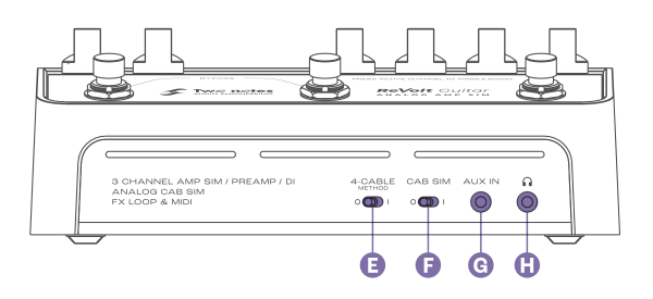
E - 4-CABLE METHOD
This switch determines the behavior of ReVolt’s effects loop alongside its bypass behavior. See the section Supercharge your amp with the 4 cable method for comprehensive setup guidelines for this feature.
F - CAB SIM
Enables the analog cabinet simulation applied to the BALANCED and Headphone outputs of ReVolt by engaging the CAB SIM switch (I Position) For ReVolt Guitar, the analog simulation is inspired by a Marshall® 4×12 Slash Signature cabinet.
G - AUX IN
Connect your music player here and control the playback level via the source’s controls. This input is stereo.
H - Headphone Output
The headphone output is a 1/8” TRS jack socket. This output is calibrated for headphones rated up to 100Ω. ReVolt’s signal is mono - the AUX IN can only be heard in stereo via headphones. The cabinet simulation applied with the CAB SIM switch can also be heard through the headphone output.
4. Back Panel
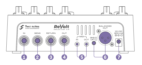
1 - IN
Connect your instrument here. The input is a ¼” TS (unbalanced) jack socket.
2 - SEND
Use this unbalanced output to connect to effects pedals or to an amp’s Instrument input when the 4-CABLE METHOD switch (E) is activated. The SEND output is a ¼” TS jack socket.
When the 4-CABLE METHOD switch is activated, and when ReVolt is bypassed (no active channel), the SEND outputs the dry/unaffected guitar signal to the connected amplifier/device.
3 - RETURN
Use this unbalanced input to connect the output of any external effects to ReVolt, or connect the amp’s effects loop SEND to this input when the 4-CABLE METHOD switch (E) is activated. The RETURN input is a ¼” TS jack socket panel-mount connector.
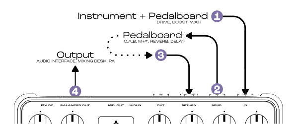
When using effects pedals (delay, reverb, etc.), ensure the 4-CABLE METHOD is set to O. The processed signal of the effects will be heard when a channel is active on ReVolt.
4 - OUT
This unbalanced output (¼” TS jack) sends the dry signal of ReVolt’s channels - the CAB SIM is never applied to this output.
5 - MIDI IN/OUT
The MIDI In/Out sockets are ⅛” TRS jack panel-mount connectors. One TRS 1/4” jack to MIDI type A adapter cable is provided with ReVolt.
By default, ReVolt sends and receives Program Change (PC) messages from 1 to 7 . Edit all MIDI messages through ReVolt’s dedicated MIDI Setup menus (see the MIDI SETUP section of the manual for more details)
6 - BALANCED OUT
Use this balanced output to connect directly to your audio interface, monitors or mixing desk. Apply speaker simulation to this output with the CAB SIM Switch (F). The GND/LIFT switch eliminates unwanted hum caused by ground loops when activated.
7 - MAINS POWER ADAPTOR
Connect the provided power supply here. ReVolt needs 12V DC, 600mA and a center negative polarity to work.
USE CASES
1. Go Direct - On Stage & In The Studio
Use ReVolt to go-direct to mixing desks audio interfaces when on stage or recording respectively.
Using the BALANCED OUT with the CAB SIM engaged, send your complete guitar tone out of ReVolt. Further refine your tone by adding effects in the FX Loop of ReVolt.
You can also use a C.A.B. M+ connected to either the effects loop or OUT output to add our class-leading DynIR cabinet emulation to your rig.
2. Supercharge Your Amp With The 4 CABLE METHOD
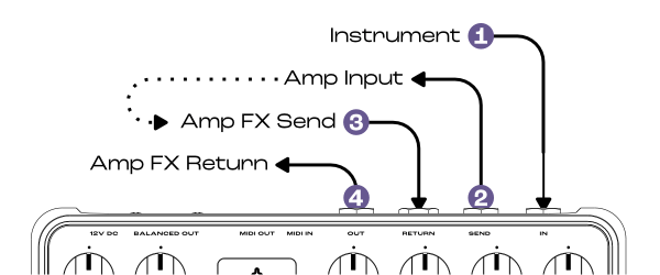
If your amp is equipped with an effects loop, add ReVolt’s 3 channels to your amplifier’s channel specification. Engage the 4-CABLE METHOD on ReVolt, and combine ReVolt’s effects loop with the amp’s using the following connectivity guidelines.
- Connect your instrument/pedalboard to ReVolt’s IN
- Connect ReVolt’s SEND to the amp’s input
- Connect the amp’s effects loop send to the ReVolt’s RETURN
- Connect ReVolt’s OUT to the amp’s effects loop return
When ReVolt is bypassed, the dry guitar signal passes through the amp’s input and all the amp’s features/tone shaping are unaltered by ReVolt’s all-analog processing. When a channel is activated on ReVolt, the signal passes through the instantiated ReVolt preamp and companion tone stack, feeding only the amplifier’s power amp.
3. Take Your Tone Further With Wall of Sound
Connect the OUT output to your audio interface’s instrument input and combine ReVolt’s channels with Wall of Sound for enhanced cabinet simulation and additional post-processing effects.
Alternatively, disengage the CAB SIM, and use the BALANCED OUT with the audio interface’s mic preamp to record / process your signal with Wall of Sound.
SPECIFICATIONS
| Input | Size | Function / Specifications |
|---|---|---|
| IN | 6.35mm (1/4“) | Jack 6.35 mm (1/4”), unbalanced (TS, Tip/Sleeve) Impedance: 1MΩ |
| SEND | 6.35mm (1/4”) | Jack 6.35mm (1/4“), unbalanced (TS) Max output level: 11 dBu Impedance : 10kΩ |
| RETURN | 6.35mm (1/4“) | Jack 6.35mm (1/4“), unbalanced (TS) Max input level: 11dBu Impedance: 1MΩ Unbuffered, directly connected to Output when active |
| OUT | 6.35mm (1/4”) | Jack 6.35mm (1/4”), unbalanced (TS) Max output level: 11dBu Impedance: 300Ω |
| MIDI IN | 3.5mm (⅛”) | MIDI adapter cable Pinout: TIP=DIN 5 RING=DIN 4 SLEEVE=DIN 2 |
| MIDI OUT | 3.5mm (⅛”) | MIDI adapter cable Pinout: TIP=DIN 5 RING=DIN 4 SLEEVE=DIN 2 |
| GND LIFT | PUSH BUTTON | With the switch engaged it opens (disconnects) the connection between the ReVolt ground and the balanced audio output. |
| BALANCED OUT | XLR | XLR, balanced Impedance: 600Ω balanced, 300Ω unbalanced Max output level: 11dBu |
| 12V DC 600 mA | 2.1mm | Mains power adaptor DC Jack 2.1mm, negative center Input voltage: 12V DC Power consumption: approx. 6W Current draw: 600mA |
Advanced Functionality
1. Using the Setup Menu System
The setup menu is entered by holding down footswitch A and providing power to the device. When the setup menu is entered, the “tube window” will show the “first page” color.
- Press footswitch B to go to the next page.
- Press footswitch A to go to the previous page.
- Press footswitch C to enter a page.
- When the last page is selected, pressing footswitch B will select the first menu and the channel LEDs will flash quickly.
- When the first page is selected, pressing footswitch A will select the last menu and the channel LEDs will flash quickly.
- To enter a sub-menu, press the footswitch C button. The “tube-window” color will quickly blink.
- Once in a sub-menu, a power-cycle is required to exit.
- Valid settings are saved immediately
- Every time there is a number displayed to the user, it is done using the channel LEDs:
- Channel A : 100s
- Channel B : 10s
- Channel C : units
- Example: Number 123 is reported as 1 blink on channel A, 2 blinks on channel B and 3 blinks on channel C. The same process applies for error messages.
2. Menu Pages
Setup Menu Pages and Color Reference
The Page order is as follows:
- FX loop defaults : Pink
- Boost defaults : Green
- MIDI Monitor : White
- MIDI learn : Blue
- MIDI Channel : Orange
- MIDI PC Number : Purple
- FX LOOP MIDI CC : Turquoise
- BOOST MIDI CC : Yellow
- FW VERSION / Factory Reset : Red
3. MIDI SETUP
3.1 MIDI Monitor
The MIDI monitor uses the RGB LED behind the tube window to display the type of MIDI (PC, CC, or SYSEX) message received.
Typical behavior when a MIDI message is received is as follows:
- Valid message received, channel is wrong - show ORANGE
- Valid message received, PC - GREEN, CC - BLUE. The message # is displayed on the channel LEDs.
- Valid SYSEX received, display PINK. The message byte count, if less than 999, is displayed on the channel LEDs.
3.2 MIDI Learn
This menu can be used to set the MIDI PC number associated with each ReVolt Channel (including the Boost state per channel) and the Bypass Mode The Default MIDI PC values are as follows :
| Channel A | Channel A+boost | Channel B | Channel B+boost | Channel C | Channel C+boost | Bypass | |
|---|---|---|---|---|---|---|---|
| Guitar | PC 0 | PC 1 | PC 2 | PC 3 | PC 4 | PC 5 | PC 6 |
| BASS | PC 0 | - | PC 1 | - | PC 2 | - | PC 3 |
While in this setup menu, pressing a footswitch will set the pedal for the message to be programmed: Corresponding LEDs will light for 1s before displaying the current assigned PC number for this channel
3.2.1 Assigning "Channel On" PC (A, B, or C)
- Press A, B, or C - the corresponding channel LED will momentarily turn ON
- After one second, ReVolt will use the channel LEDs to flash the currently assigned PC number.
- The user can now send a valid MIDI PC message
- If Valid - the channel LED will remain solid for 1 second, then ReVolt will begin flashing the newly assigned PC number
- If Invalid - if the PC message is already assigned to another channel function - the channel LEDs will flash 3 times. The device remains in assignment mode and will await a valid PC message.
3.2.2 Assigning "Channel On BOOST" PC (A, B, or C)
- Press A, B, or C 2 times, the “tube window” indicates boost mode (very red) - the corresponding channel LED will momentarily turn ON
- After one second, ReVolt will use the channel LEDs to flash the currently assigned PC number.
- The user can now send a valid MIDI PC message
- If Valid, the channel LED will remain solid for 1 second, then ReVolt will begin flashing the newly assigned PC number
- If Invalid - if the PC message is already assigned to another channel function - the channel LEDs will flash 3 times. The device remains in assignment mode and will await a valid PC message.
3.2.3 Assigning BYPASS PC
- Press A+B: All LEDS will blink for 2*500ms.
- After one second, ReVolt will use the channel LEDs to flash the currently assigned PC number.
- The user can now send a valid MIDI PC message
- If Valid, the channel LED will remain solid for 1 second, then ReVolt will begin flashing the newly assigned PC number
- If Invalid - if the PC message is already assigned to another channel function - the channel LEDs will flash 3 times. The device remains in assignment mode and will await a valid PC message.
3.3 MIDI PC Number
Please note, by default the MIDI PC start value is set to 0.
This menu page allows the user to configure the starting MIDI PC message value when pressing one of the 3 channel footswitches. PC messages sent are as follows:
| Channel A | Channel A+boost | Channel B | Channel B+boost | Channel C | Channel C+boost | Bypass | |
|---|---|---|---|---|---|---|---|
| Guitar | PC number | PC number + 1 | PC number + 2 | PC number + 3 | PC number + 4 | PC number + 5 | PC number + 6 |
| BASS | PC number | - | PC number + 1 | - | PC number + 2 | - | PC number + 3 |
The current PC number is displayed via the channel LEDs
The PC number can be incremented by pressing footswitch A,B or C
FS A = -1 FS B = +1 FS C = +10
Note: If you program the pedal to go further than max permitted MIDI PC starting value (122 for ReVolt Guitar, 125 for ReVolt Bass), it will revert back to the first option and vice versa.
3.4 MIDI CHANNEL
Please note, by default ReVolt’s MIDI Channel configuration is set to 17 (OMNI)
This menu page allows the user to configure which MIDI Channel is utilized by ReVolt. The available MIDI Channel values within ReVolt are as follows:
| 0 | 1 to 16 | 17 |
|---|---|---|
| MIDI OFF, only THRU active | MIDI Messages are received and sent on this channel number | OMNI : MIDI messages are received on all channels and sent on channel 1 |
The current channel number is displayed via channel LEDs
The channel number can be incremented by pressing footswitch A, B or C
FS A = -1 FS B = +1 FS C = +10
Note: If you program the pedal further than the max allowed number (17), it will remain set at 17; the same behavior is consistent for minimum values.
4. BOOST Defaults
Please note, by default ReVolt’s Boost configuration is set to off for all channels.
This menu page allows the user to configure the Boost state and Boost behavior per channel. Two independent modes are available: BOOST DEFAULT and BOOST MEMO. If the user toggles the 4CM switch it changes between the two modes.
4.1 BOOST DEFAULT MODE
Note, this is an option for how ReVolt Guitar’s boost behaves. Users can either choose Boost Default Mode or Boost Memo Mode. Boost Default Mode sets the default state of each channel - e.g. boost on or off from power-up. Within this mode, the Channel LED is on if the boost is active when entering the channel. If off, the boost is inactive. Press the corresponding footswitch to toggle the default boost state for each channel.
4.2 BOOST MEMO MODE
Using this mode allows the user to configure the default boost state on a per channel basis; once configured, when returning ReVolt to normal operation (by rebooting the device), the boost status will be memorized on a per-channel basis. Upon entering this mode, all the LEDs on ReVolt Guitar will blink at the same time.
If the boost memo mode is selected, and when ReVolt is returned to normal operation, if the boost is set to on for a specific channel, it will stay set for this channel until deactivated.
5. BOOST CC Number
Please note, by default ReVolt’s Guitars default Boost CC is set to 15.
Using this menu allows the user to configure the default boost MIDI CC number. The CC number is displayed and incremented in the same manner that the MIDI PC number is actioned. For further details, please see the “PC Number” section.
Top Tip: If attempting to assign a CC number that has already been assigned, all LEDs will blink and ReVolt will automatically default to the next available MIDI CC number.
6. FX Loop
6.1 Default State
Please note, by default ReVolt’s default FX Loop State is set to All On.
Using this setup menu allows the user to select the FX loop state for each channel, when not using the 4CM mode.
Once inside the menu, if the Channel LED shows ON, the FX loop is active for this channel. Press the corresponding channel footswitch to toggle between the ON/OFF FX loop states for the associated channel.
6.2 FX Loop CC
Please note, by default ReVolt’s default FX Loop CC state is set to 14.
Using this setup menu allows the user to select the FX Loop CC state per channel. The CC number is displayed and incremented in the same manner that the MIDI PC number is actioned. For further details, please see the “PC Number” section.
7. Firmware Version / Factory Reset
Using this setup menu allows the user to view the current Firmware version installed on the ReVolt unit as well as options to action a Factory Reset.
Upon entering this setup menu, the current Firmware Version number is displayed on ReVolt’s channel LEDs.
To action a Factory Reset, press Channel A’s footswitch 3 times. With each press, the Channel LED color shifts to white. After completing the sequence, the tube window will show white and the Channel LEDs remain on for 2 seconds indicating that the factory reset has occurred correctly. Once the Factory Reset has been actioned, the unit will resume to display the current Firmware Version across the channel LEDs.

